- HOME
- Products
- Basic materials
- Technical conditions
- Technological equipment
- CAD CAM
- The Laser Photoplotter
- CNC drilling and routing
- UV Laser drilling and routing
- Laser Tannlin TX PROi
- Direct plating
- Vyplňování otvorů | Planarizer
- Surface readjustments
- Surface finishes
- Galvanic processes
- Digital Direct Imaging
- The etching
- Solder mask and silkscreen
- Inspections of PCB
- Controlled impedance
- Multilayer lamination
- Contour fabrication
- Analytical Laboratory
- PCB Designs
- PCB assembly
- Terms and Conditions
- Preislist
- Contact
- kariéra
Contour fabrication
PCB Routing
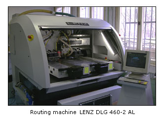
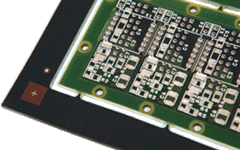
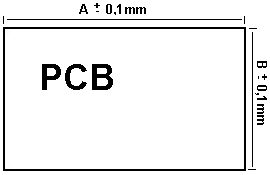
The coordinate routing machine LENZ DLG 460-2 AL is in reality a routing machine combined with a coordinate drill with automated loader, identical with DLG 550-2 AL. Special routing spindles allow setting of higher cutting speeds of tools and thus achievement of smooth routed edge. Each spindle is fitted with an individually controllable Z axis. The routing machine is also fitted with optical camera. The accuracy of dimension is ± 0,1mm and the smallest radius in the edge region is 0,5mm. It is also possible to deliver the boards in panels, cut by a routing with bridges (for automated assembling). The number, location and size of bridges and specification of the technological environment is to be determined by the customer himself or herself. If not, the boards are routing with four bridges of the size of 0.5 - 1mm, according to the size of the multipanel and thickness of the basic material.
|
|
|
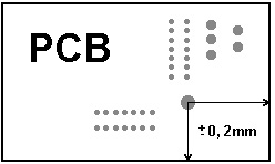
If the customer, while placing the order, demands keeping the tolerance of the outline’s position towards drilling, it is necessary to append a dimensioned technical drawing to the order placement. In the Gerber data, a contour line must be clearly indicated together with the information whether the exact dimension corresponds with the centre or with the inside edge of the contour line.
|
|
|
The tolerance of the outline position towards the DPS pattern is ± 0,2 mm + the tolerance of the given construction class ( construction classes).
V-scoring
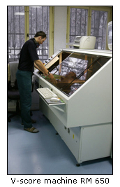 The V-scoring device RM 650 from the company HML with program-controlled Z axis is an ideal solution for final treatment of multiple PCB panels intended for mass assembling. The device allows scoring of panels of sizes from 120 x 120mm to 650 x 650mm with the thickness of material from 0,5 to 3,2mm. The controlled Z axis allows setting of various depths of the groove in one cut and in any place on the panel. Fastening by means of mechanical pins with a pressure heel ensures sufficiently its stable position and in this way it prevents spontaneous movement of the board and thus its impairment.
The controlling software allows new setting of the program within few minutes and thus it is ideal both for piece production and serial production. The standard thickness of the residual material for scored panels is 1/3 of the total thickness of the material. This setting is appropriate especially for division of individual patterns by a special tool (for instance cutting disc). If you divide the individual PCB manually, it is convenient to set a deeper grove, especially with small patterns. Please consult an appropriate setting of the depth of the grove with the technician of the order reception.
|
|
Basic parameters of the device RM 650 : work surface : 120x120mm - 650x650mm thickness of the material : 0,5 - 3,2mm diameter of the fastening pin : 3,0mm minimal distance between the pin - first groove : 8mm depth of the grove : programmierbar minimal thickness of the rest of material : 0,2mm |



 company adress :
 place of business :


