- HOME
- Products
- Basic materials
- Technical conditions
- Technological equipment
- CAD CAM
- The Laser Photoplotter
- CNC drilling and routing
- UV Laser drilling and routing
- Laser Tannlin TX PROi
- Direct plating
- Vyplňování otvorů | Planarizer
- Surface readjustments
- Surface finishes
- Galvanic processes
- Digital Direct Imaging
- The etching
- Solder mask and silkscreen
- Inspections of PCB
- Controlled impedance
- Multilayer lamination
- Contour fabrication
- Analytical Laboratory
- PCB Designs
- PCB assembly
- Terms and Conditions
- Preislist
- Contact
- kariéra
Maximal current load of wire
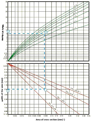
Allowable current load of the wire as a function of temperature rise
| Example of the calculation : Required current is 8 Amps with maximal 30°C temperature rise of. How wide wire shall I use on board with 35µm Cu foil? In graph we find point A, which refers to 8 Amps current and intersect with 30°C temperature rise curve (point B ). Then we connect point B with bottom curve, which refers to Cu foil of 35µm (point C ). From this point C we can read required width of the wire (point D ). In this case it is 2.5 mm More information can be found here : www.ultracad.com |
Wire width equation (Rovnice výpočtu šíře vodiče) :
I = 0.0150(DT 0.5453)(A 0.7349) for norm IPC-D-275 (inner layers wires)
I = 0.0647(DT 0.4281)(A 0.6732) for norm IPC-D-275 (outer layers wires)
where:
I = maximal current in Amps
DT = temperature rise in °C
A = Area of cross section of the wire in square mils


 company adress :
 place of business :


